This document introduces how to implement SLAMWARE solution into your own Robot system.
Content
| Table of Contents | ||||
|---|---|---|---|---|
|
R&D Process Introduction
SLAMWARE is SLAMTEC's high-performance indoor positioning and navigation solution based on the RPLIDAR 360 ° Lidar. The following is a typical SLAMWARE Core development robot chassis development process, the process is divided into three phases: Evaluation, Verification, Integration.
...
SLAMWARE Core is a navigation and positioning module product that can be ordered in batches. It adopts Mini PCI-E physical interface and other customized electrical interface. Users can design the chassis board by themselves with an integration of SLAMWARE Core indoor positioning & navigation solution.
Evaluation with SLAMWARE SDP
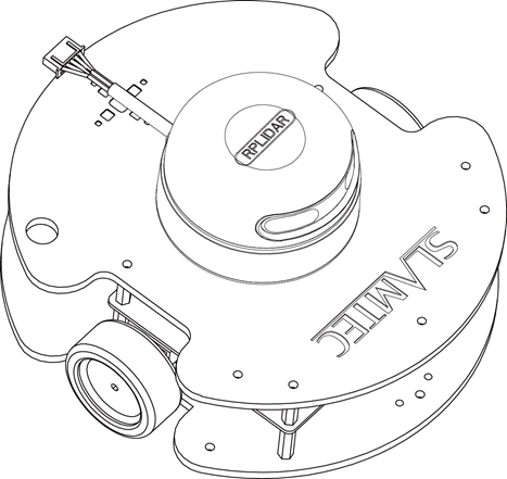
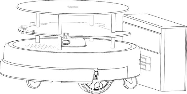
The SLAMWARE SDP series empowers customers to quickly evaluate the performance of SLAMWARE solutions, in the meanwhile providing a foundation platform to validate customer prototype systems. The SDP series has two different models, both models requires no additional hardware integration, you can evaluate SLAMWARE performance directly by using RoboStudio software.
SLAMWARE SDP Mini | SLAMWARE SDP | |
线稿图 |
|
|
Size(Diameter*Height) | 185mm * 100mm | 400mm * 230 mm |
Weight | About 0.85kg | About 5.1kg |
Sensors |
|
|
Advantages |
|
|
Shortcomings |
|
|
Applications |
|
|
Evaluation with ZEUS platform
ZEUS is a generic service robot platform from SLAMTEC that integrates SLAMWARE positioning and navigation solutions. It also incorporates a number of features that are required in a commercial environment:
...
The platform greatly simplifies the development of a service robot and reduces the time consumption from R&D to production. For more information, please refer to Zeus Robot Platform product page.
General Introduction of System Structure
Generally speaking, a robot consists of 2 systems, chassis system and application system. The chassis mainly performs functions such as motion, and obstacle avoidance, which is more general. The application system mainly focusses on logic such as voice recognition, face recognition, which is closely related to the service of the final deployment scenario. Slamware solution is also divided into two parts, Slamware Core and Slamware SDK. Slamware Core is a hardware module with SLAM algorithm,located in the robot chassis, responsible for the establishment of the map, autonomous navigation, real-time positioning, automatic obstacle avoidance, automatic recharge and other functions; Slamware SDK is a set of software libraries, working in the application layer, The interface allows customers to control the chassis, for example, to move to the specified point, access to the built map, access to current position and other functions. Currently Slamware SDK supports four mainstream application platforms: Windows, Linux, Android, iOS.
Next is the instructions of how to integrate Slamware solution into chassis system and the application system.
Chassis System
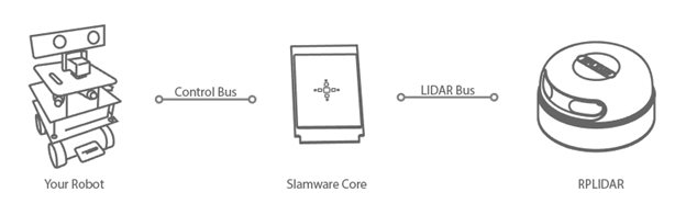
The robotic chassis based on the SLAMWARE solution consists of three main components: RPLIDAR, Slamware Core module, Chassis (including chassis control MCUs, sensors, motor controllers, etc.). The SLAMWARE Core connects to the chassis control MCU via the Control Bus, and connects to RPLIDAR via LIDAR Bus. This is a smallest system based on the SLAMWARE solution.
Please note that the lidar is connected to the Slamware Core directly, not via the robot chassis MCU.
Hardware Integration
There are 2 ways of Integration:
...
It’s recommended to integrate Slamware Core directly in mass production. the Slamware solution with breakout is more adapted to prototypes, cause the breakout was originally designed only for evaluation, no production-level test and certification was made.
SLAMWARE Breakout Introduction
SLAMWARE Breakout is a development board used for fast evaluation of Slamcore. It integrates an STM32F103VET6 MCU and you can find I/O layout and definition below. By connecting breakout to chassis system with necessary electric devices (sensors, motor drives etc.), a robot hardware prototype could be realized in a short time.

Integration based on Slamware Breakout
The block diagram shows the Slamware breakout- based robot chassis system. The main integration work is to connect the Breakout board to various peripherals. Users need to decide the integrated peripherals based on their actual requirements.
- Motor drive circuit
- Bumper (optional)
- Cliff sensor (optional)
- Ultrasonic sensor (optional)
- Automatic recharge circuit (optional)

Direct SLAMWARE Core Integration
To directly integrate Slamware Core,you need to choose a compatible MCU for chassis control(for example,STM32F103VET6 of the Slamtec breakout). The MCU communicates with Slamware Core using Control Bus protocol, steering motors, also collecting sensor data. MCU and Slamwre Core will keep continuous communication. Once the communication is disconnected, Slamware Core will consider chassis is working abnormally and them will stop working after waiting for a certain period of time.
...
- Power supply integration
- RPLidar interface design
- Chassis MCU and SLAMWARE Core integration
- Motor drive circuit design
- Automatic recharge(optional)
- Ultrasonic sensors(optional)
- Cliff sensors(optional)
- Depth Camera(optional)
Structure Integration
Users need to make a mechanical design when integrating slamware solution. The size of SLAMWARE Core and breakout could be found in data sheet.
Firmware Integration
Integration based on SLAMTEC reference code
A reference firmware using IAR compiler and STM32F103VET6 is provided by SLAMTEC which allows customers to develop their own robot chassis firmware. Customers can select some of the peripherals according to the actual status of the robot for integration, integration steps are as follows:
...
IAR version should be V7.6 above.
Integration based on existing firmware
Customers who already have their own chassis firmware systems can also integrate SLAMWARE solutions by implementing Control Bus Protocol:
- Control Bus protocol integration
- Functions regarding power management
- Functions regarding motion control
- Functions regarding ultrasonic sensor
- Functions regarding bumpers
- Functions regarding automatic recharge
- Polling Command function realization (Command sent from chassis to SLAMWARE Core)
- Event Notification function realization (Event sent from SLAMWARE Core to chassis)
- Functions regarding health management
Application layer
Communication between application layer and chassis
Application layer and chassis communication connection
...
It is recommended to use a wired internet connection between the application layer and chassis. For Android device, there is only one allowed network connection which makes it impossible to connect additional external Internet. To find a solution for this, you can refer to solution here.
Chassis control with Slamware SDK
Windows
For Windows users, we provide a 32bit Windows SDK. Integration Windows platform has the following requirements:
...
- IDE configuration
- Connection management and automatic reconnection
- Local data cache
- Map display
- Robot motion control
Linux
For Linux users,we support the following platform and compiler versions:
...
- IDE configuration
- Connection management and automatic reconnection
- Local data cache
- Map display
- Robot motion control
iOS
For IOS users,we provide SDK with Objective-C interface,the following steps are recommended for the integration:
- IDE configuration
- Connection management and automatic reconnection
- Local data cache
- Map display
- Robot motion control
Android
For Android users,we provide SDK using Java,the following steps are recommended for the integration:
- IDE configuration
- Connection management and automatic reconnection
- Local data cache
- Map display
- Robot motion control
Conclusion
The above is the main work involved for Slamware Solution, if you have problems with more specific process, please refer to the application notes and data sheets on wiki.slamtec.com