Table of Contents
General Introduction
SLAMWARE module communicate with chassis using Control BUS protocol. Chassis should upload a corresponding configuration to SLAMWARE module, otherwise wrong positioning and navigation will happen.
Parameters regarding installation and direction:
1) Installation position and direction of RPLidar.
2) Installation of SLAMWARE module.
3) Installation position of Bumper/Cliff sensor/Sonar.
the above devices should be configured following the chassis coordinate system. The detail of installation will be explained in the following section of this document. In addition, other parameters regarding wheel span, robot size, automatic recharge could be also configured with slamware_config_tool.
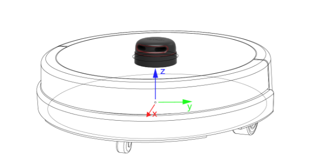
Chassis Coordinate System
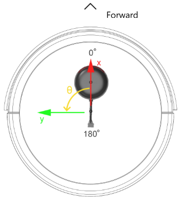
In the chassis coordinate system, the positive X points to the forward direction of robot, the positive y points to the left, the positive Z points to the top. In an angle coordinate system, the x positive is the 0°, and an counterclockwise rotation will be considered as positive(see pictures below).
Robot Configuration
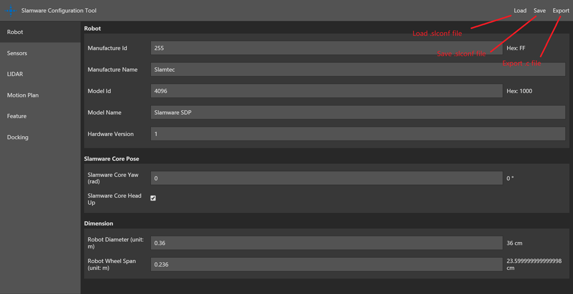
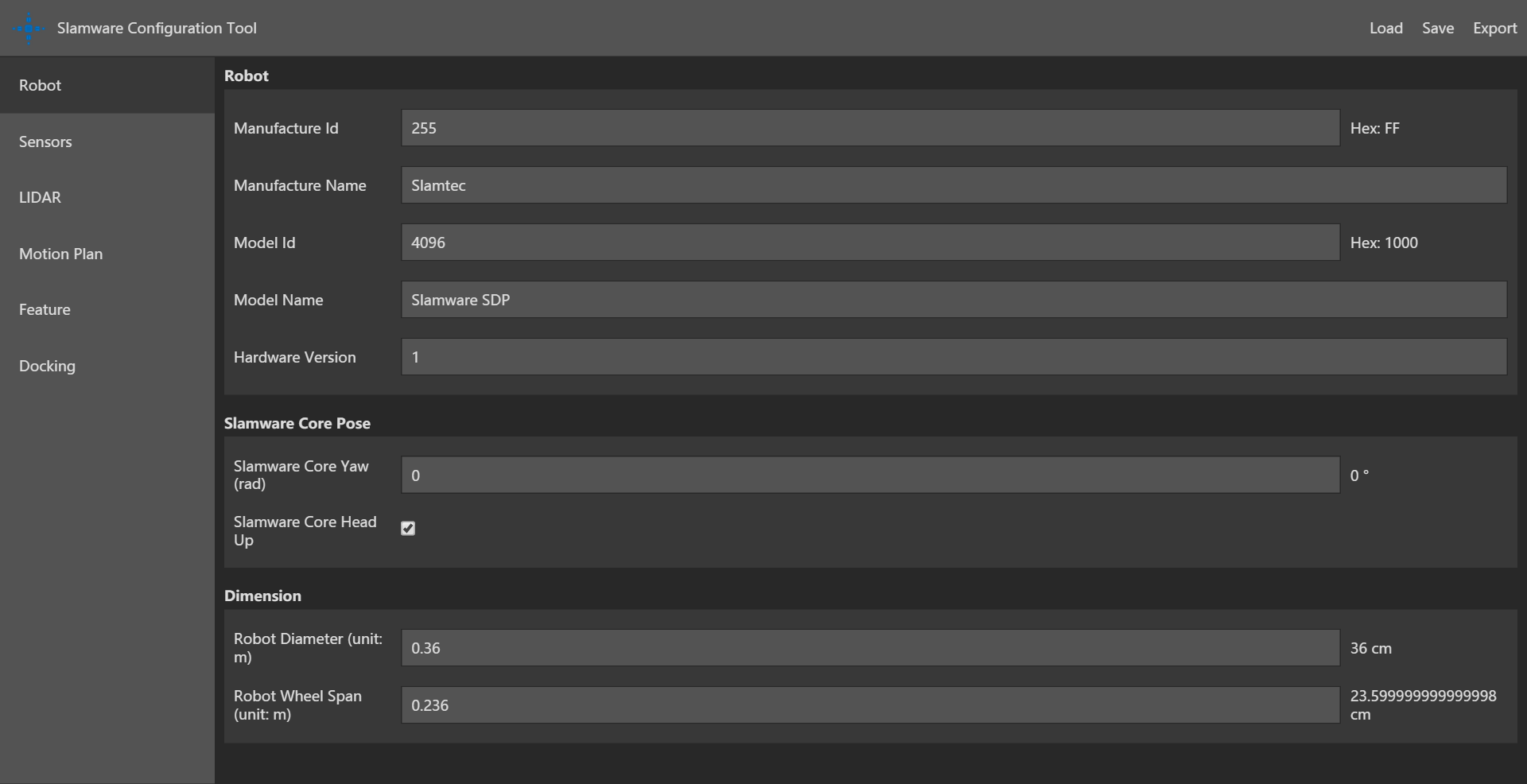
On the Robot page, users can configure the basic parameters of the robot. This page consist of 3 sections, Robot,Slamware Core Pose and Dimension. Currently Robot section have nothing to do with robot behavior, you can keep the default settings.
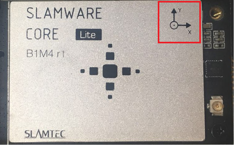
Slamware Core Configuration
On the Robot page, user can configure Slamware core pose. The ‘yaw ’indicates the counterclockwise angle difference between axis x of Slamcore coordinate system(see picture below) and axis x of the chassis coordinate system. The default setting is slamware core head up checked, which means the white side is on the top. if your slamcore has an reverse installation, please do not check the "slamware core head up" item.
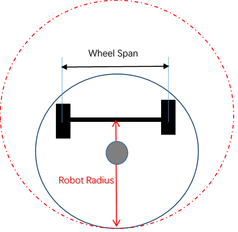
Robot Diameter and Wheel Span Configuration
The diameter of the robot circumscribed circle should be considered as the Robot Diameter. This value is used to filter out obstacles detected by the lidar within the size of the chassis and prevent the objects on the chassis from misdirection and wrong navigation. Robot Wheel Span is the diameter of the circumscribed circle of the wheel of the robot, including the two-wheel and three-wheel omni-directional wheels. The measurement should start from the center of the tire thickness begins to measure.
Bumper/Sonar/Cliff Senor Configuration
In the Sensors page, you can configure sensor IDs, Types, position of installation. Please note that the sensor ID should be unique, which means you cannot assign the same ID number to two sensors, not even for sensor of different types. The coordinate system here is the chassis coordinate system.
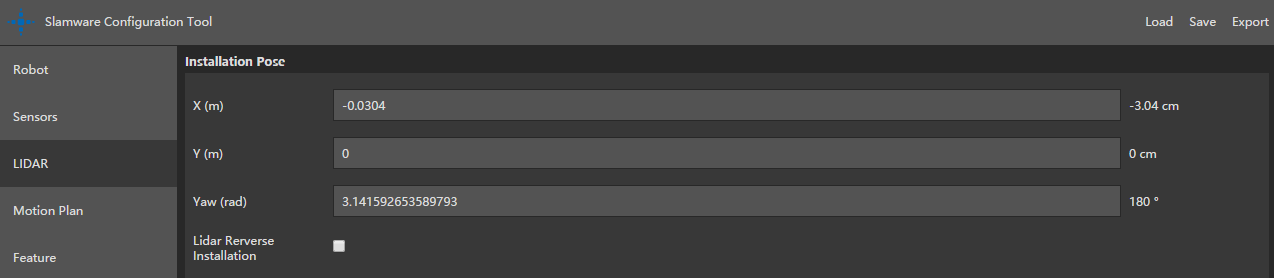
LIDAR configuration
In the LIDAR page, you can configure the position of installation of RPLidar. Please note that the “yaw” represents the angle difference between 0 angle of Lidar(see figure XX) and x positive of chassis coordinate system. If you check the “ Lidar Reverse Installation”, the RPLidar should be installed up-side down.
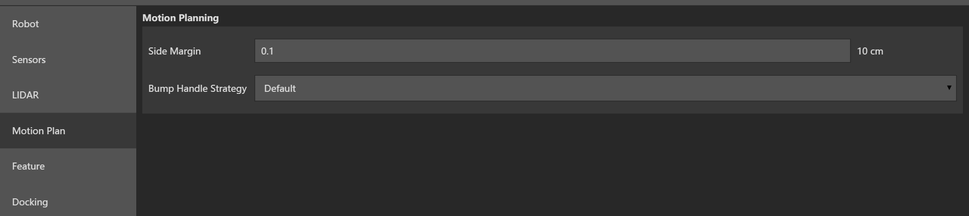
Motion Plan Configuration
On Motion Plan page, uses can configure paramters regarding obstacle avoidance. Due to the uneven shape of the robot, the obstacle avoidance range may not only be limited to the range of the chassis, the side margin is applied to adjust the size of the obstacle avoidance range. The obstacle avoidance range is a circle with a diameter of "Robot diameter + 2 * side margin"
Bump Handle Strategy is set to Default, that is, when bumper is triggered, robot start to move back and find other paths available.
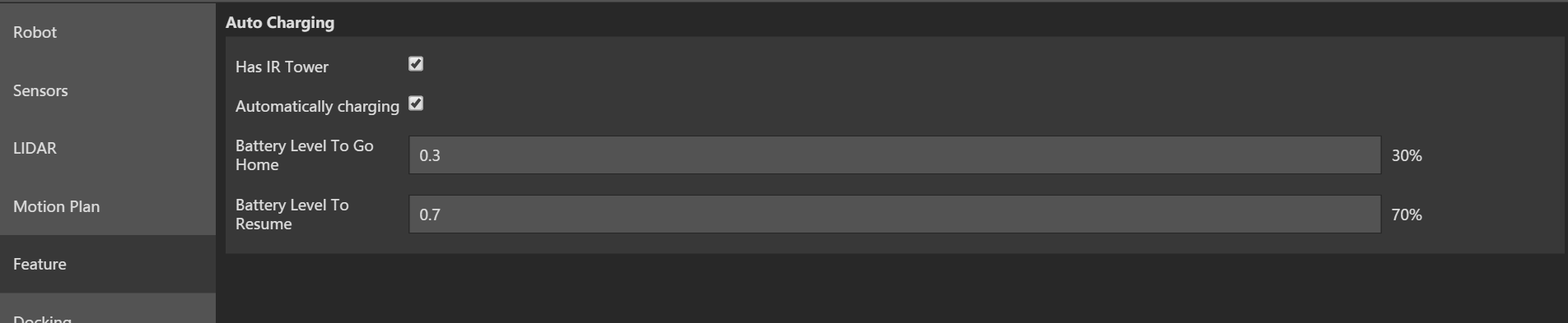
Feature Configuration
On this page, users could configure the parameters related to infrared charging. this section is not related to motion control and obstacle avoidance, you can keep the default settings. If you have questions about the following parameters, please contact SLAMTEC technical support.
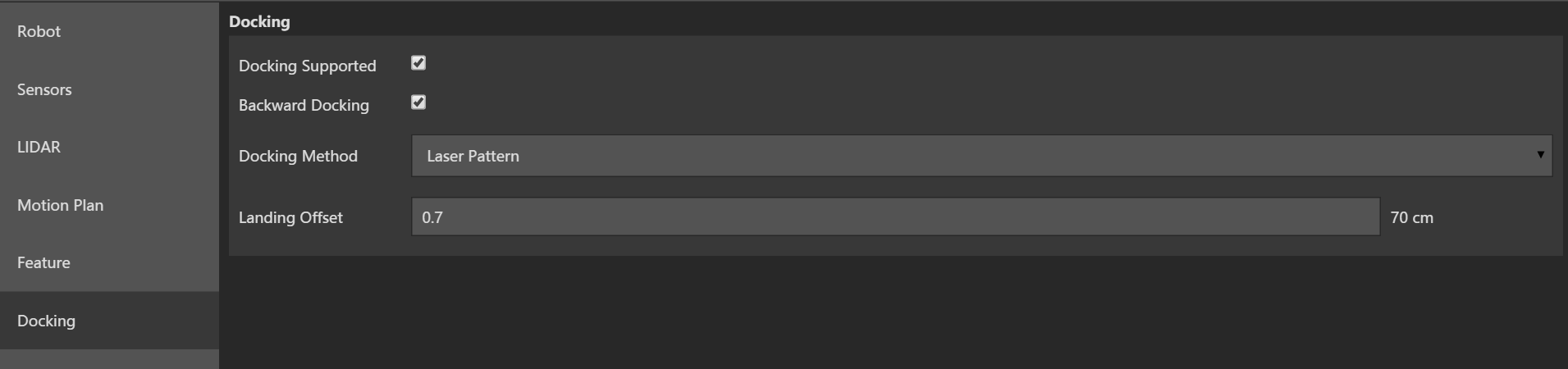
Docking Configuration
On this page, users could configure the parameters related to charging behavior. This section is not related to motion control and obstacle avoidance, you can keep the default settings. If you have questions about the following parameters, please contact SLAMTEC technical support.
Save Configuration File
There are 3 items on the top-right corner on the interface:
1. Load: you can load existing *.slconf file into this configuration tool.
2. Save: you can save the configured parameters as a *.slconf file.
3. Export: with this function, you can export a *.c file contains all the configuration that you made. To upload this configuration file to your project, please replace the corresponding file with this one. For example, if you are using reference code from SLAMTEC, you can replace the sdp_mini.c with the new file.