本页内容
概述
三全向轮的底盘在机器人界也有非常广泛的应用,在SLAMWARE集成的过程中,三全向轮底盘的集成难度相对更高,故提供此文档用以协助集成。
底盘类型
三全向轮底盘的常用布局有2种,一种是1个全向轮在前,2个在后(即下图中的a),另一种是2个全向轮在前,1个在后(即下图中的b)
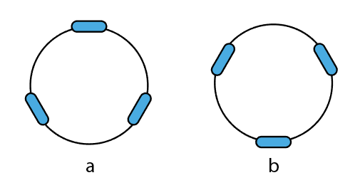
在接下来的文章中,将针对这两种常用底盘做一个说明。
定义
机器人坐标系
所有跟机器人运动有关的计算均在机器人坐标系中进行:
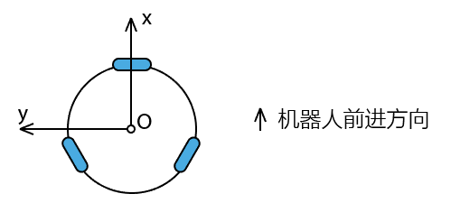
如图所示,机器人前进的正前方为x轴正方向,机器人左侧为y轴正方向,机器人的中心点的地面为坐标系的原点(O)
机器人运动控制指令
SLAMWARE Core模块采用统一的全向速度指令来对机器人进行运动控制,其坐标系如下:
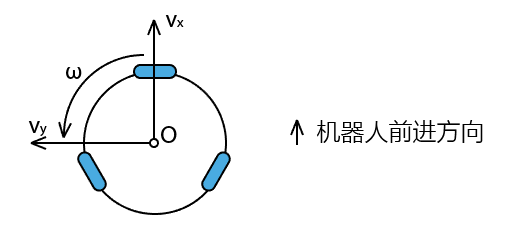
机器人往前方移动的速度为Vx,往左方平移的速度为Vy,逆时针旋转的角速度为ω。
同理,如果需要机器人向后移动,那么Vx为负值;向右移动,Vy为负值;顺时针旋转,则ω为负值。
这些速度和角速度的计量单位均为公制单位,即分别为米每秒,和弧度每秒。
注意:角速度的单位是弧度每秒,而非角度每秒,在实际使用中,需要根据实际单位进行换算。
轮组速度定义
根据轮组布局不同,轮组的速度定义如下图所示
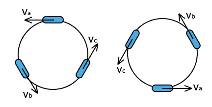
Va,Vb和Vc分别表示各个轮子的线速度,以让机器人发生逆时针旋转的方向为正,单位依然是米每秒
机器人位移定义
SLAMWARE在向底盘下达运动指令的同时,需要底盘上报机器人轮组的位移信息。
该位移信息由三部分组成,分别是Dx,Dy,Dθ,定义如下:
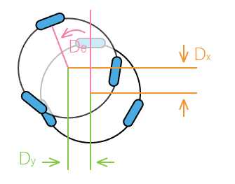
同样的,按照机器人的坐标系,如果机器人向前移动了,则Dx为正,向左移动了,则Dy为正,逆时针旋转了,则Dθ为正。
对应的每个轮子上的线位移分别是La,Lb,Lc
涉及指令
针对传统的两轮差动式的底盘,可以直接使用SLAMWARECORECB_CMD_GET_BASE_MOTOR_DATA和SLAMWARECORECB_CMD_SET_BASE_MOTOR两条指令来操作。
针对其他类型的底盘,涉及到的指令主要是SLAMWARECORECB_CMD_SET_V_AND_GET_DEADRECKON指令,即0x41指令。
它的请求报文的内容是:
typedef struct _base_set_velocity_request
{
    _s32 velocity_x_q16;
    _s32 velocity_y_q16;
    _s32 angular_velocity_q16;
} __attribute__((packed)) base_set_velocity_request_t;
所以对应的:
base_set_velocity_request_t req;


float vx = req.velocity_x_q16 / 65536.f;
float vy = req.velocity_y_q16 / 65536.f;
float omega = req.angular_velocity_q16 / 65536.f;
而这个指令的响应报文如下:(由于历史原因,响应报文中dx ,dy的单位是mm, dtheta的单位是度)
typedef struct _base_deadreckon_response
{
    _s32 base_dx_mm_q16;
    _s32 base_dy_mm_q16;
    _s32 base_dtheta_degree_q16;
    _u8  status_bitmap;
} __attribute__((packed)) base_deadreckon_response_t;
对应的代码如下:
#ifndef PIf
#	define PIf 3.14159265f
#endif

float dx, dy, dtheta;

base_deadreckon_response_t resp;

resp.base_dx_mm_q16 = (_s32)(dx * 1000 * 65536);
resp.base_dy_mm_q16 = (_s32)(dy * 1000 * 65536);
resp.base_dtheta_degree_q16 = (_s32)(dtheta * 180 / PIf * 65536);
resp.status_bitmap = 0; // 这个字段用以报告轮组的异常状态,请务必都填0
计算公式
备注:所有公式中的R表示的是机器人的旋转半径,单位是米(也就是轮子距离机器人中心的距离)
速度分解
将SLAMWARE Core下发的速度指令分解到各个轮子上。
布局a:1个全向轮在前,2个全向轮在后
Va = Vy + R * ω
Vb = - Vx * cos(30°) - Vy * sin(30°) + R * ω
Vc = Vx * cos(30°) - Vy * sin(30°) + R * ω
布局b:2个全向轮在前,1个全向轮在后
Va = - Vy + R * ω
Vb = Vx * cos(30°) + Vy * sin(30°) + R * ω
Vc = -Vx * cos(30°) + Vy * sin(30°) + R * ω
里程累积
当底盘收到上述指令以后,需要首先获得三个轮子在上一次收到这条指令和这一次收到这条指令之间的线位移,分别记作Da,Db,Dc
布局a:1个全向轮在前,2个全向轮在后
Dθ = (Da + Db + Dc) / R / 3
Dx = (- Db * cos(30°) + Dc / cos(30°)) / 2
Dy = (- Db * sin(30°) - Dc / sin(30°) + Da) / 3
布局b:2个全向轮在前,1个全向轮在后
Dθ = (Da + Db + Dc) / R / 3
Dx = (Db / cos(30°) - Dc / cos(30°)) / 2
Dy = (-Da + Db / sin(30°) + Dc / sin(30°)) / 3
示例代码
// 假设机器人是布局a

#ifndef PIf
#	define PIf 3.14159265f
#endif

#define COS30f	0.86602540f
#define SIN30f  0.5f
#define R		0.18f  // robot radius: 18cm

static float wheel_odometer[3];

static void on_set_v_and_get_deadreckon(const base_set_velocity_request_t& req, base_deadreckon_response_t& resp)
{
    // calculate response
    float current_wheel_odometer[3];
    motion_get_wheel_odometer(current_wheel_odometer);

    float da = current_wheel_odometer[0] - wheel_odometer[0];
    float db = current_wheel_odometer[1] - wheel_odometer[1];
    float dc = current_wheel_odometer[2] - wheel_odometer[2];

	memcpy(wheel_odometer, current_wheel_odometer, sizeof(current_wheel_odometer));

    float dx = (-db / COS30f + dc / COS30f) / 2
	float dy = (da - db / SIN30f - dc / SIN30f) / 3
	float dtheta = (da + db + dc) / R / 3

	resp.base_dx_mm_q16 = (_s32)(dx * 1000 * 65536);
	resp.base_dy_mm_q16 = (_s32)(dy * 1000 * 65536);
	resp.base_dtheta_degree_q16 = (_s32)(dtheta * 180 / PIf * 65536);
	resp.status_bitmap = 0; // 这个字段用以报告轮组的异常状态,请务必都填0

	// calculate wheel speed
	float vx = req.velocity_x_q16 / 65536.f;
	float vy = req.velocity_y_q16 / 65536.f;
	float omega = req.angular_velocity_q16 / 65536.f;

	float va = vy + R * omega;
	float vb = - vx * COS30f - vy * SIN30f + R * omega;
	float vc = vx * COS30f - vy * SIN30f + R * omega;

	motion_set_wheel_speed(va, vb, vc);
}